![Home Automation Using Arduino [Beginner Guide]](https://smartify.in/wp-content/uploads/2017/12/ArduinoMain.jpg)
Home Automation Using Arduino [Beginner Guide]
Do you want to automate your home? Ever wished to control your appliances with a swipe on your phone? Or do you want to learn how to build automation device for yourself?
In this tutorial, we’ll explore how you can control a lamp, fan or any other electrical appliance in your space using an Arduino. At the end of the project, you will be able to control the connected load from your smartphone.
Quick Economics:
The whole setup takes less than 15 minutes to configure and would cost less than $30. Moreover, the incremental cost of adding electrical appliance comes down to only $1.5/device, which is quite affordable for experimentation.
Required Material:
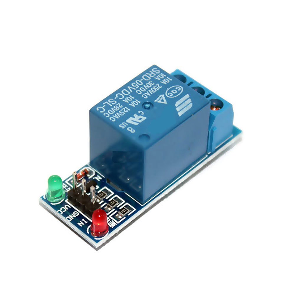 | Solid State Relay | × | 1 | |||
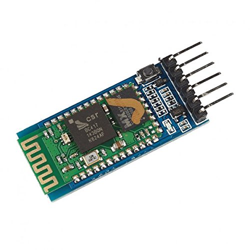 | HC 05 Wireless Bluetooth Module | × | 1 | |||
 | Lamp | × | 1 | |||
 |
| × | 1 | |||
 |
| × | 1 | |||
 |
| × | 1 | |||
 |
| × | 1 | |||
 |
| × | 1 |
Software:
- Arduino IDE.
Note: If you are using an iOS device, you won’t be able to directly control the connected load via Bluetooth. Here is an alternative tutorial for controlling devices connected to Arduino from your iPhone.
Circuit Diagram
How to Connect Bluetooth HC-05 to Arduino
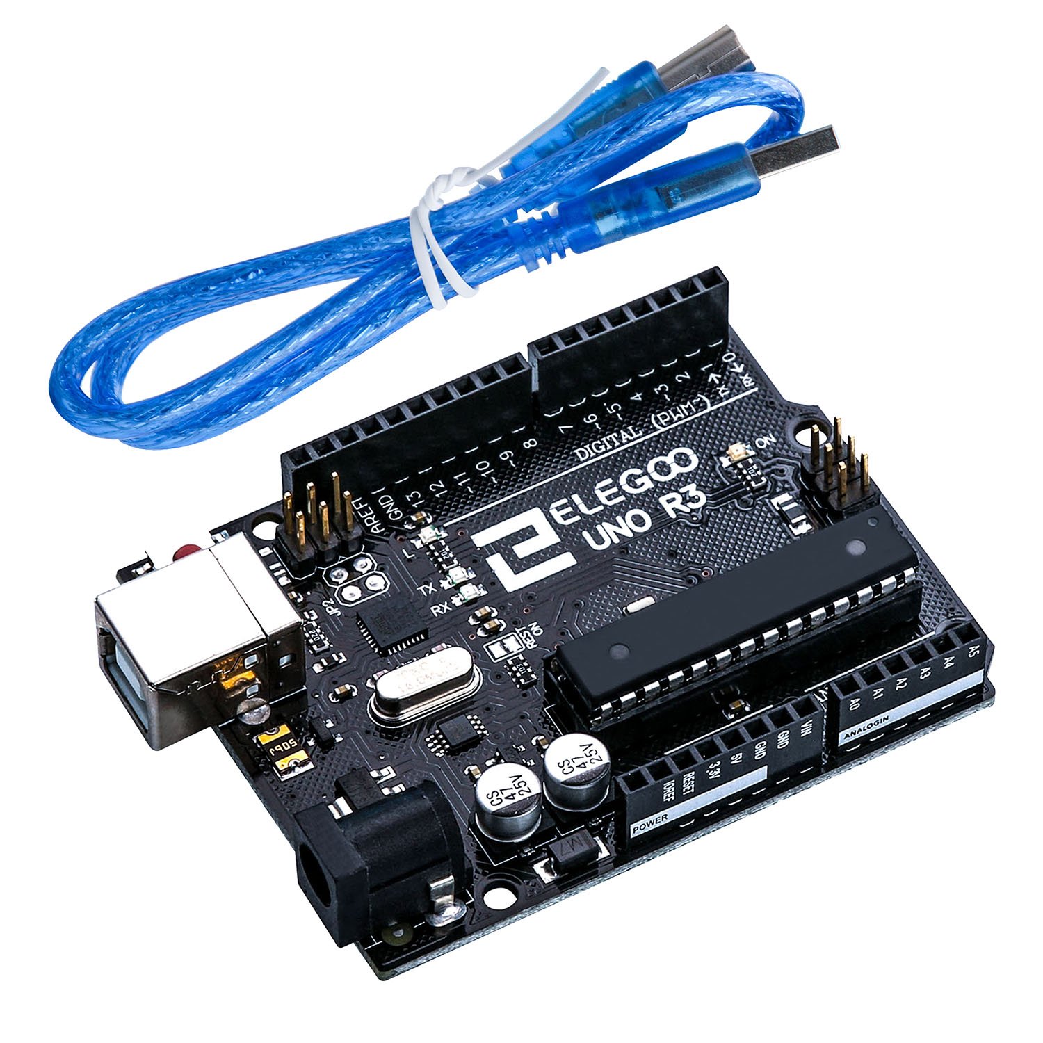
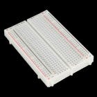
- Connect 5V and GND pin of Arduino to the bus strips on the breadboard as shown in the circuit diagram.
- To connect HC-05 module with Arduino, insert its 5V and GND pins to the bus strips on the breadboard. Note: In case HC-05 module supports 3.3V, please power it using the 3.3 V supply from Arduino.
- Connect the TXD pin on the HC-05 module with the RXD pin (Pin 0) of Arduino.
- TXD on HC-05: Transmit data from the Bluetooth transceiver.
- Pin 0 on Arduino (RXD): Receive data on Arduino two-way by connecting these pins, we are establishing a two-way communication between Arduino and HC-05, so that we can turn the device get on/off with the command properly.
- Next, as the receiver data lines on HC-05 are 3.3V tolerant, we need to convert the 5V input signal from Arduino into a 3.3 V signal. While it can be achieved easily through a bi-directional logic level converter, we’re using a voltage divider to convert the 5V input signal into a 3.3 V signal.
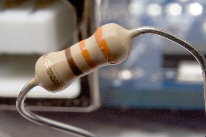
- Voltage Divider: Connect 1k ohm and 2.2k ohm resistors across the GND and TXD on Arduino, and we obtain the 3.3 V tolerant input directly from the intersection of the two resistors.
Bluetooth Test: Checkpoint
Quick Test:
Once you have connected the HC-05 module with the Arduino, you can power the Arduino with the 12V DC supply or USB cable. If the red and blue LEDs on HC-05 are blinking, you have successfully paired the Bluetooth module with Arduino.
You can also check the Bluetooth connectivity status using the State pin on Arduino.
Setting up the Relay Circuit
Once you have configured the setup on Arduino, the next step is to connect the load with our relay module i.e. the lamp (in our case). Here’s a simple circuit that explains how you need to wire the connections:
Let’s take a step back and understand what we’re doing here. As shown in the above diagram, the relay module works as an electronic switch. We are connecting this in series so that we can open and connect the circuit from the micro-controller module.
Here’s how you can wire up the relay module with Arduino:
 Firstly, connect the 5V and GND pins to the bus terminals on the breadboard.
Connect the IN1 pin on the relay board with PIN 4 of Arduino.
In case you have a multi-channel module (2, 4 or 8 channels), you can connect IN2, IN3 … IN(n) with different digital pins of Arduino, and repeat the below steps for configuring other pins.
After connecting the signal pins to Arduino, we need to connect the AC load to the relay module. Now, if you look carefully at the terminal block on the relay module, you would find three slots.
Let’s understand what these slots really mean:
C | Common |
NC | Normally Connected |
NO | Normally Open |
COM – Common Terminal:
It is the center terminal, Power to the load is connected to this terminal.
NO -Normally open:
It acts like a switch. Since it remains normally open, there will be no contact between COM and NO, When we trigger the relay module, it connects to COM by the electromagnet inside the relay and load gets the supply, which powers up the light.Thus the circuit is closed until we trigger the state to low in the relay.
NC-Normally Closed:
It is always in contact with COM when the relay is not powered.When the relay is triggered it opens the circuit.
In the steady state (when the relay is off), the COM port is connected to NC (Normally Connected) port, which means if you connect the bulb on the NC terminal, it will stay ON even when the relay is OFF, as the circuit is already completed (That’s why it’s called “normally connected”).
For our use-case, we want to turn on the bulb only when we send a signal from a smartphone.That’s the reason we connect the load on the NO (Normally Open) terminal, so that when the relay is triggered from the Arduino, the contact brush flicks from NC to NO terminal, thereby completing the circuit.
Note: Electricity is dangerous. If you wish to use other electrical appliances. Make sure proper precautions regarding relay constraints and voltage are taken.
CODE :
#define RELAY_ON 0
#define RELAY_OFF 1
#define RELAY_1 4
char data = 0;
void setup() {
// Set pin as output.
pinMode(RELAY_1, OUTPUT);
// Initialize RELAY1 = off. So that on reset it would be off by default
digitalWrite(RELAY_1, RELAY_OFF);
Serial.begin(9600);
Serial.print(“Type: 1 to turn on the bulb. 0 to turn it off!”);
}
void loop() {
if (Serial.available() > 0) {
data = Serial.read(); //Read the incoming data and store it into variable data
Serial.print(data); //Print Value inside data in Serial monitor
Serial.print(“\n”); //New line
if(data == ‘1’){
digitalWrite(RELAY_1, RELAY_ON);
Serial.println(“Bulb is now turned ON.”);
}
else if(data == ‘0’){
digitalWrite(RELAY_1, RELAY_OFF);
Serial.println(“Bulb is now turned OFF.”);
}
}
}
Here’s an explanation of the code:
First, we initialize the relay first in setup() method. Then, wait for input on the Serial port in the loop() method.
If ‘1’is received input, we turn on the relay.
If ‘0’ is received, we turn off the relay.
Now, when you’ll try to upload the code to your Arduino, while the HC-04 module is connected, you’ll get the following error:
avrdude: stk500_getsync() attempt 1 of 10: not in sync: resp=0x00
An error occurred while uploading the sketch
That’s because Arduino UNO operates on UART, which means it has common TX-RX lines. It can’t communicate with your computer and Bluetooth module at the same time.
To solve the error, simply unplug the jumper wire connected to Pin 0 of Arduino (Rx pin), and re-attempt to upload code on Arduino. You should now be able to update the code successfully. The reason the simple hack works is that Arduino is no longer receiving data from two sources, and therefore can receive the code from the computer.
Arduino Bluetooth Controller: Connecting to a Smartphone
Now that we have configured the hardware and successfully uploaded the code, our next step is to control the setup from a smartphone. In order to that, you’ll need to download the Arduino Bluetooth Controller app on your Android device. In case you’re controlling multiple relays, you can also download the Arduino Bluetooth Control app from broxcode.
Since we are connecting a single relay, we are using the Arduino Bluetooth Controller app. Here’s how you can configure your Android device to send commands to Arduino:
Step-1: Open the app on your smartphone. It will ask for Bluetooth permissions. Click ‘Ok’.
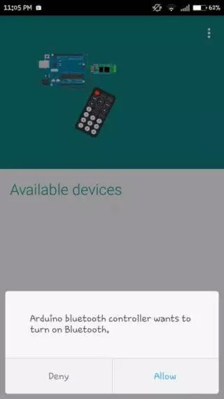
Step-2: Next, it will list all the available devices in your vicinity. Click on HC-05.

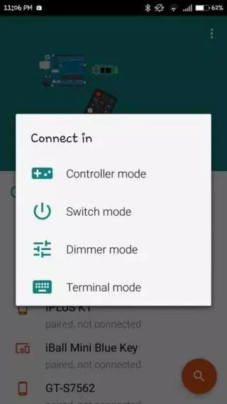
Step-3: Once you click on the device, you would be connected to the transceiver. It would now prompt you to enter the mode that you wish to use. Select “Switch” mode.
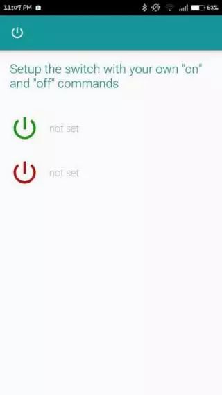
Step-4: You should be redirected to the following screen. Click on the “Settings” tab in the top-right corner of the screen.

Step-5: It will ask you to set values for ON and OFF. Enter ‘1’ in the ON text box and ‘0’ in the OFF text box. Click Submit.
And we are done.
Let’s have a look at the final setup:
Using the above setup, you can turn any electrical appliance into a smart device that can be controlled from your smartphone. While we used a single relay in the example, you can expand the use-case with an optocoupler 8-channel relay.
Note: To keep things simple, we have used a simple Bluetooth app that allows you to control only a single load, but in case you wish to control more devices, you can use a use a more sophisticated Bluetooth control app or write your own custom Android app.
Future add-ons for your Smart-home setup:
We laid the basic groundwork for controlling electrical loads using an Arduino controller and smartphone in this example. However, what we have managed to achieve so far is just one tiny use-case of home automation.
We can do a lot more with home automation, like:
Schedule appliances to turn on/off at preset times.
Set the mood with brightness controller in your room-lights.
Speed up/down fans to pre-defined levels.
Control IR devices for security purpose (for instance: a burglar alarm to send notifications).
Lock/Unlock doors from your comforters.
Trigger scenes from a central controller.
We’ll be exploring more detailed use-cases in our future articles. If you wish to receive more such tutorials directly on your mailbox, please subscribe to our mailing list. We send emails only once a month and promise to not spam you. Thank you for reading 🙂
P.S: If you have any questions regarding the above setup, please feel free to reach us out.