Do you want to automate your home? Ever wished to control your appliances with a swipe on your phone? Or do you want to learn how to build automation device for yourself?
In this tutorial, we’ll explore how you can control a lamp, fan or any other electrical appliance in your space using an Arduino. At the end of the project, you will be able to control the connected load from your smartphone.
Quick Economics:
The whole setup takes less than 15 minutes to configure and would cost less than $30. Moreover, the incremental cost of adding electrical appliance comes down to only $1.5/device, which is quite affordable for experimentation.
Note: If you are using an iOS device, you won’t be able to directly control the connected load via Bluetooth. Here is an alternative tutorial for controlling devices connected to Arduino from your iPhone.
Circuit Diagram
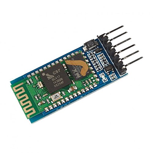
How to Connect BluetoothHC-05to Arduino
Connect 5V and GND pin of Arduino to the bus strips on the breadboard as shown in the circuit diagram.
To connect HC-05 module with Arduino, insert its 5V and GND pins to the bus strips on the breadboard. Note: In case HC-05 module supports 3.3V, please power it using the 3.3 V supply from Arduino.
Connect the TXD pin on the HC-05 module with the RXD pin (Pin 0) of Arduino.
TXD on HC-05: Transmit data from the Bluetooth transceiver.
Pin 0 on Arduino (RXD): Receive data on Arduino two-way by connecting these pins, we are establishing a two-way communication between Arduino and HC-05, so that we can turn the device get on/off with the command properly.
Next, as the receiver data lines on HC-05 are 3.3V tolerant, we need to convert the 5V input signal from Arduino into a 3.3 V signal. While it can be achieved easily through a bi-directional logic level converter, we’re using a voltage divider to convert the 5V input signal into a 3.3 V signal.
Voltage Divider: Connect 1k ohm and 2.2k ohm resistors across the GND and TXD on Arduino, and we obtain the 3.3 V tolerant input directly from the intersection of the two resistors.
Bluetooth Test: Checkpoint
Quick Test:
Once you have connected the HC-05 module with the Arduino, you can power the Arduino with the 12V DC supply or USB cable. If the red and blue LEDs on HC-05 are blinking, you have successfully paired the Bluetooth module with Arduino.
You can also check the Bluetooth connectivity status using the State pin on Arduino.
Settingup the RelayCircuit
Once you have configured the setup on Arduino, the next step is to connect the load with our relay module i.e. the lamp (in our case). Here’s a simple circuit that explains how you need to wire the connections:
Let’s take a step back and understand what we’re doing here. As shown in the above diagram, the relay module works as an electronic switch. We are connecting this in series so that we can open and connect the circuit from the micro-controller module.
Here’s how you can wire up the relay module with Arduino:
Firstly, connect the 5V and GND pins to the bus terminals on the breadboard.
Connect the IN1 pin on the relay board with PIN 4 of Arduino.
In case you have a multi-channel module (2, 4 or 8 channels), you can connect IN2, IN3 … IN(n) with different digital pins of Arduino, and repeat the below steps for configuring other pins.
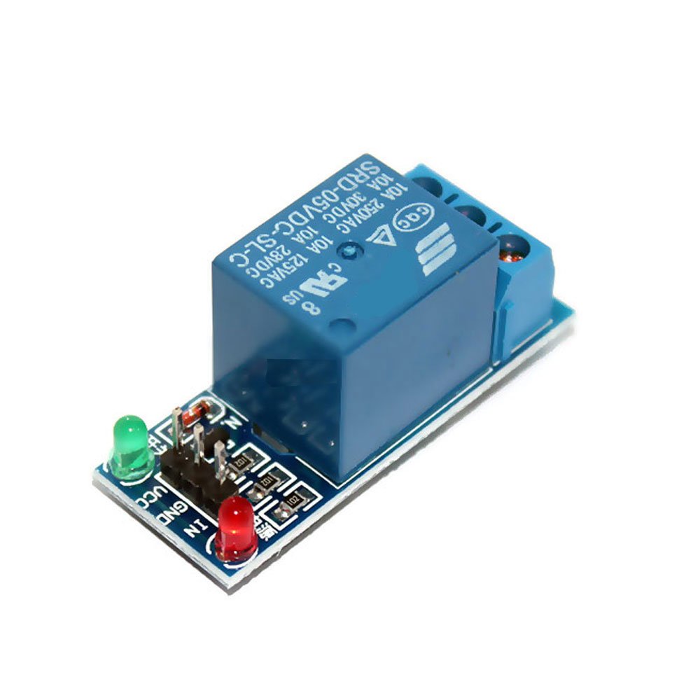
After connecting the signal pins to Arduino, we need to connect the AC load to the relay module. Now, if you look carefully at the terminal block on the relay module, you would find three slots.
Let’s understand what these slots really mean:
C
Common
NC
Normally Connected
NO
Normally Open
COM – Common Terminal:
It is the center terminal, Power to the load is connected to this terminal.
NO -Normally open:
It acts like a switch. Since it remains normally open, there will be no contact between COM and NO, When we trigger the relay module, it connects to COM by the electromagnet inside the relay and load gets the supply, which powers up the light.Thus the circuit is closed until we trigger the state to low in the relay.
NC-Normally Closed:
It is always in contact with COM when the relay is not powered.When the relay is triggered it opens the circuit.
In the steady state (when the relay is off), the COM port is connected to NC (Normally Connected) port, which means if you connect the bulb on the NC terminal, it will stay ON even when the relay is OFF, as the circuit is already completed (That’s why it’s called “normally connected”).
For our use-case, we want to turn on the bulb only when we send a signal from a smartphone.That’s the reason we connect the load on the NO (Normally Open) terminal, so that when the relay is triggered from the Arduino, the contact brush flicks from NC to NO terminal, thereby completing the circuit.
Note:Electricity is dangerous. If you wish to use other electrical appliances. Make sure proper precautions regarding relay constraints and voltage are taken.
CODE :
#define RELAY_ON 0
#define RELAY_OFF 1
#define RELAY_1 4
char data = 0;
void setup() {
// Set pin as output.
pinMode(RELAY_1, OUTPUT);
// Initialize RELAY1 = off. So that on reset it would be off by default
digitalWrite(RELAY_1, RELAY_OFF);
Serial.begin(9600);
Serial.print(“Type: 1 to turn on the bulb. 0 to turn it off!”);
}
void loop() {
if (Serial.available() > 0) {
data = Serial.read(); //Read the incoming data and store it into variable data
Serial.print(data); //Print Value inside data in Serial monitor
Serial.print(“\n”); //New line
if(data == ‘1’){
digitalWrite(RELAY_1, RELAY_ON);
Serial.println(“Bulb is now turned ON.”);
}
else if(data == ‘0’){
digitalWrite(RELAY_1, RELAY_OFF);
Serial.println(“Bulb is now turned OFF.”);
}
}
}
Here’s an explanation of the code:
First, we initialize the relay first in setup() method. Then, wait for input on the Serial port in the loop() method.
If ‘1’is received input, we turn on the relay.
If ‘0’ is received, we turn off the relay.
Now, when you’ll try to upload the code to your Arduino, while the HC-04 module is connected, you’ll get the following error:
avrdude: stk500_getsync() attempt 1 of 10: not in sync: resp=0x00
An error occurred while uploading the sketch
That’s because Arduino UNO operates onUART, which means it has common TX-RX lines. It can’t communicate with your computer and Bluetooth module at the same time.
To solve the error, simply unplug the jumper wire connected to Pin 0 of Arduino (Rx pin), and re-attempt to upload code on Arduino. You should now be able to update the code successfully. The reason the simple hack works is that Arduino is no longer receiving data from two sources, and therefore can receive the code from the computer.
Arduino Bluetooth Controller: Connecting to a Smartphone
Now that we have configured the hardware and successfully uploaded the code, our next step is to control the setup from a smartphone. In order to that, you’ll need to download theArduino BluetoothControllerapp on your Android device. In case you’re controlling multiple relays, you can also download theArduino BluetoothControlapp from broxcode.
Since we are connecting a single relay, we are using theArduino BluetoothControllerapp. Here’s how you can configure your Android device to send commands to Arduino:
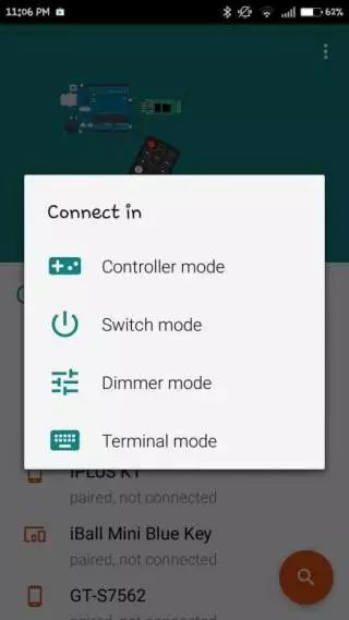
Step-1: Open the app on your smartphone. It will ask for Bluetooth permissions. Click ‘Ok’.
Step-2: Next, it will list all the available devices in your vicinity. Click on HC-05.
Step-3: Once you click on the device, you would be connected to the transceiver. It would now prompt you to enter the mode that you wish to use. Select “Switch” mode.
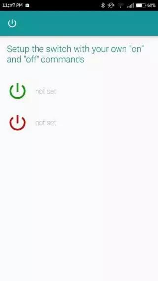
Step-4:You should be redirected to the following screen. Click on the “Settings” tab in the top-right corner of the screen.
Step-5:It will ask you to set values for ON and OFF. Enter ‘1’ in the ON text box and ‘0’ in the OFF text box. Click Submit.
And we are done.
Let’s have a look at the final setup:
Using the above setup, you can turn any electrical appliance into a smart device that can be controlled from your smartphone. While we used a single relay in the example, you can expand the use-case with anoptocoupler8-channel relay.
We laid the basic groundwork for controlling electrical loads using an Arduino controller and smartphone in this example. However, what we have managed to achieve so far is just one tiny use-case of home automation.
We can do a lot more with home automation, like:
Schedule appliances to turn on/off at preset times.
Set the mood with brightness controller in your room-lights.
Speed up/down fans to pre-defined levels.
Control IR devices for security purpose (for instance: a burglar alarm to send notifications).
Lock/Unlock doors from your comforters.
Trigger scenes from a central controller.
We’ll be exploring more detailed use-cases in our future articles. If you wish to receive more such tutorials directly on your mailbox, please subscribe to our mailing list. We send emails only once a month and promise to not spam you. Thank you for reading 🙂
P.S: If you have any questions regarding the above setup, please feel free to reach us out.
How to Turn Your Raspberry Pi into Amazon Echo in $15 (Alexa)
Amazon’s nifty little AI-powered voice-assistant, Alexa, that can process contextual queries in human voice has taken the world by storm. It’s been barely two years since Amazon launched its powerful voice service, and the company has already sold 5 million devices, and positioned itself as the ultimate home automation gadget.
The primary reason behind the widespread popularity of AVS (Amazon Voice Service) is the powerful platform that it provides to collaborators for developing interactive voice apps. Perhaps, that’s the reason why Amazon’s Alexa conquered CES 2017, and how from Ford to Martian, from LG to Whirlpool, nearly every conceptual design had in-built Alexa integration.
As you can now control a wide array of home automation devices using just your voice, it makes sense for every smart home enthusiast to buy Alexa. However, I’m a big-time DIY person, and I thought it would be really exciting to see if it’s possible to install Alexa on my Raspberry Pi.
While I expected the setup to be a complicated process, it turned out that the setup was fairly straightforward, In fact, I was able to complete the whole setup in less than an hour. It also cost significantly lesser than Echo (almost nothing), as I hooked up peripherals that I already had at my workplace.
<Screenshot or Affiliate Link>
Introduction
In this article, I’m going to walk you through how you can turn your Raspberry Pi into Amazon Echo. The setup requires a fair bit of technical expertise, since you’ll be running commands on Linux terminal and editing shell scripts on Raspberry Pi.
However, by the end of the guide, you would have a fully functional Amazon Echo device that can respond to your voice commands and take actions. You’ll be able to do unit conversions, check weather, get sport updates, listen to podcasts and tons of other things.
But that’s not even the best part.
Once you’re through the entire setup, you’ll be able to alter Alexa’s settings through your iPhone or Android device, just like you’ll be able to do that on a real Echo. That means you would be able to create smart skills that allow you to control connected devices, like LIFX or Nest Thermostat, with your voice. If that’s not enough, you would even be able to call a cab, order a pizza or know what’s the next item on your to-do list just by asking Alexa.
Here’s how the end setup looks like….
(Note: The PlayStation Eye camera is used for capturing the voice.)
For the project, I used all the components that I could find lying around my desk. Of course, you could get a good quality microphone, instead of a PlayStation Eye camera. I’ve connected my portable speaker through 3.5 mm port (you could use a better one!), and I’m using wireless bluetooth keyboard and mouse to program my Pi.
The whole setup cost me less than $59 (Raspberry Pi Model 3: $39 + Portable Speaker: $8 + PlayStation Eye Camera: $7). I’ve not included the cost of wireless mouse and keyboard, as you don’t require them to send voice commands (they are needed just for programming Pi).
Here’s all the stuff you’ll need for the project:
Raspberry Pi 3 (recommended) or any older version of Raspberry Pi. You can even use Raspberry Pi Zero, but you’ll need to buy an additional USB Wi-Fi adapter, for older models of Pi.
8 GB SD Card with Raspbian (Jessie) installed
Micro-USB cable (for powering Pi)
3.5 mm Bluetooth or plugged-in speaker (for hearing Alexa’s voice)
An USB microphone, like, <Affiliate Link>, for sending voice commands. However, for this demo, I have used the cheap $8 PlayStation Eye Camera, as it was laying around my desk.
Keyboard, display and mouse (for running the setup)
How to Install Alexa Voice Service on Raspberry Pi
Step 1: Setup your Raspberry Pi
The first step is to connect setup your Raspberry Pi and get it up and running. In case you haven’t already installed Raspbian on your Pi, you can go ahead and download the latest version, here. Once you have downloaded the image file, the next step is to burn the image file on your SD card. Here’s the guide you can follow to successfully create a bootable SD card with Raspbian installed.
After installing Raspbian, the next step is to connect your keyboard and mouse with Raspberry Pi. If you’re using a USB keyboard/mouse, it should be a fairly straight-forward process. However, if you’re using a wireless bluetooth mouse/keyboard set, you’ll need to pair that up with Raspberry Pi. Again, if you’re using Model 3, you don’t need to buy an external bluetooth dongle, but in case you’re using older versions, you may need to get a compatible Bluetooth adapter to get things going. Lastly, you’ll need to connect your Pi to a HDMI display, so that you’re able to see the output.
[Tip: In case you don’t want to spend money on buying an external display, mouse or keyboard, you can even connect to your Raspberry Pi using VNC (Virtual Network Computing). Here’s a guide on how to setup VNC on your Pi. ]
Once you have your Pi up and running, the next step is to configure the speakers and microphone. For that, connect your portable speaker to the 3.5 mm jack on your Raspberry Pi, and select “Analog” by right-clicking on the speaker menu on the top-right corner.
Next, connect your microphone (in my case– camera) to USB port of your Raspberry Pi, and run the following command on Terminal: alsamixer. You’ll be able to see a similar screen. Adjust the volume and sensitivity of your microphone, using arrow keys. Once you’re done, run the command sudo alsactl store to save the changed configurations.
Next, run the following sudo nano /usr/share/alsa/alsa.conf on Pi’s Terminal. It will open up an Editor window. Navigate below to the line that reads:
defaults.ctl.card 0 defaults.pcm.card 0
Change the above line to:
defaults.ctl.card 1 defaults.pcm.card 1
The above command should successfully set your speaker (connected via line-in) and microphone (connected via USB) as default.
Step 2: Register for Amazon Developer Account
Before proceeding with the installation, you’ll need to register for a free Amazon Developer Account, so that you can link your DIY Echo with Alexa Voice Service (AVS). Once you have registered, you should be able to login and see a similar dashboard:
Once you’re on the dashboard, click on Alexa in the navigation menu. It’ll give you two options– Alexa Skills Set and Alexa Voice Service. Click on “Alexa Voice Service”.
Click on “Register a Product Type”. It will ask whether you wish to register a device or an application. Click on Device.
After that, you’ll be asked to give your device a Type ID and Name. You can give it any name. For the example, we chose to name it Raspberry Pi.
Next, you’ll be asked whether you wish to create a new security profile. Click Next.
Make a note of your Client ID and Client Secret key from the below screen. You don’t need to make a note of the Security Profile ID.
Click on the “Web Settings” in the adjacent tab and once you’re on the tab, click on the “Edit” button on top-right. After you click on “Edit”, you’ll be able to add “Allowed Origins” and “Allowed Return URLs” for the the security profile. Click on “Add Another”, next to Allowed Origins, and type in: https://localhost:3000 Click on “Add Another”, next to Allowed Return URLs, and type in: https://localhost:3000/authresponse. Once you’re done, click on “Next”.
Once you’re through that, you’ll be on the “Device Details” screen. It really doesn’t matter what you enter, here. So, pick an image for your device, choose a category, type in the description, set the expected timeline, enter the number of devices you wish to commercialize, and select “No” for children product. Click on “Next” when you’re done.
In the final step, you’ll be asked to add Amazon Music to the setup. However, the service does not really work on Raspberry Pi as of now, so click on “No” to finish the setup.
Step 3: Install Alexa on Your Raspberry Pi
Now that you have a working Amazon Developer account and profile for an Alexa-powered device, it’s time to go ahead and install the voice service on your Raspberry Pi.
Open the Terminal on your Raspberry Pi and type: cd Desktop.
Type in git clone and hit Enter. The command would fetch the code files from Amazon’s repository and download them on your Desktop.
Once that’s done, type cd ~/Desktop/alexa-avs-sample-app and hit Enter.
Type in nano automated_install.sh and press Enter.
It will pull up a text editor, that would look something like this: Enter the ProductID (the Type ID that you gave for the device in the first step), ClientID and ClientSecret (the keys from the security profile). You can use the arrow keys to navigate through the editor. Once you’re done, Type Ctrl + X to save and exit.
It should bring you back to the terminal window. Type in . automated_install.sh and hit Enter.
It should open up a prompt window, where you would be asked questions on the type of installation. Type “Y” for each question (the default configuration), or you may even choose to answer them as you wish. Once you’ve answered all the questions, grab a cup of coffee, and leave the computer alone. The setup would take at least 30-45 minutes to complete.
In the end, if you can see that the log trace reads, something like this: Congratulations! You have successfully installed Alexa on your Raspberry Pi. But wait, the setup has not yet finished. You need to now run the companion service, followed by triggering the client and wake service.
Step 4: Run Alexa Companion Service
Just like every application needs a server to communicate with, you need to first setup Alexa Companion service. The companion service acts as a gateway between Amazon’s servers and your personalized Echo device.
You can start the companion service by typing in the following command:
cd ~/Desktop/alexa-avs-sample-app/samples/companionService && npm start
It should start the companion service, and you should be able to see the message, which would read something like this: “Listening on Port 3000”
That means, you have successfully started the companion service, and it’s now listening to incoming requests. Leave the window open [WARNING: Do not close the window, as we want the server to be running, when we start our client service.], and proceed further.
Step 5: Run the sample app and authenticate your account
The next step is to start the client service, which can send requests to your companion service. In order to do that, open second Terminal window (File > New Window), and type in the following command:
cd ~/Desktop/alexa-avs-sample-app/samples/javaclient && mvn exec:exec
When you enter the command, a dialog box will pop up, asking you to authenticate your device. Click on Yes. It should open a browser window [Tip: In case the window does not appear, copy the link in the dialog box and open it in the browser].
In the meanwhile, a second popup would open in the Java app, asking you to click “Ok”, if you have already signed into Amazon. DO NOT click on “Ok”, yet.
First, login into your Amazon account, and click on “Allow” when AVS asks for your permission. If the setup goes right and you have entered the right credentials (ProductID, ClientID and ClientSecret key), you’ll be able to see the following screen, which reads “device tokens ready”:
Once you see the above screen, close the browser and click on the “Ok” pop-up box in the Java app. Now, your Raspberry Pi has the necessary tokens to communicate with Amazon’s server and process your voice commands. You can test that by manually pressing the Listen button on the client application and saying “Hi” to Alexa.
But, wait, that’s not how Alexa works. Shouldn’t you be able to call her from anywhere? Well, there’s one final step left to get there ….
Step 6: Trigger the wake word agent
Now that we have the client and server running, we need to create a daemon service that actively listens to user commands and triggers the client service, when they call for “Alexa”.
The wake word agent is already installed on your Raspberry Pi, as part of the initial setup, so you just need to invoke it. There are two options for wake word software, Sensory and KITT.AI. While both of them are available for free, Sensory expires after 90 days.
But, since we are running the setup for experimental purpose, let’s use Sensory. Open a new terminal window and type in the following command:
cd ~/Desktop/alexa-avs-sample-app/samples/wakeWordAgent/src && ./wakeWordAgent -e sensory
That’s it. Once you enter the above command, the wake word engine would start running, You can go ahead and try it out by saying “Alexa”. You should be able to hear a beep, indicating that it’s listening to your question. Try asking her something, like, “How’s the weather?”, “What’s in the news?”, or even “How far is Mars from Earth?”
Debugging Issues
It happens to the best of us. Sometimes, you just end up getting stuck at an error, and have no idea where to go. But here are some of the most common errors and workarounds for setting up Alexa voice service for your Raspberry Pi:
Error page on authentication If you’re getting an authentication error when you try to give permissions to your client from the browser, it’s likely that you have entered the wrong combination of Product ID, ClientID and ClientSecret. Double check it with what you have on your AVS account. Make sure your Product ID is the Device ID for your Raspberry Pi and NOT your Security Profile ID.
Build failure on mvn exec:exec If you’re getting build failure error when you execute mvn exec:exec for your client application, it’s possible that not all dependencies listed in the POM file have been downloaded on your machine. The obvious reason for this is that your setup skipped downloading some files (Network error?), or you’re trying to install the service on Ubuntu or any other version of Linux (that is currently not supported).
java.util.concurrent.TimeoutException The error usually occurs, when you send a voice command to Alexa, but it takes too long to complete. It’s mostly a network issue, and the best trick, which has worked for most people, is to just restart Pi, network or Alexa client. It’s really not a setup issue, but a communication problem with the sever.
Unable to find definition ‘cards.bcm2835.pcm.surround51.0:CARD=0’ The error occurs when you’ve improperly configured your microphone or sound card. Depending on the device that you’re using, you might need to set it up with your Raspberry Pi. Read the following thread for more information.
Make sure AVS client is running The above error occurs, if you accidentally closed your client or server window, while triggering the wake agent service. Make sure that you have three terminal windows open while you’re running the setup.
Taking it Forward
As part of the tutorial, we have provided the boilerplate code for getting Amazon Echo up and running on your Raspberry Pi. If you’re interested in taking the project a step further, you can go ahead and make the set up a little more sophisticated.
To give you some ideas, you can write a bash script that automatically runs the alexa service every time your Raspberry Pi starts up, so that you don’t have to manually run commands on Terminal every time.
Further, you can even go ahead and try to integrate the iOS or Android companion app with AVS, so that you can run customized skills and see how third-party integrations work on the platform.
Did it work out for you?
Stuck? Having fun? Built something awesome? I’m excited to know how was your experience installing Alexa on Raspberry Pi. Please feel free to share your comments, feedback or suggestions in the comments section below.
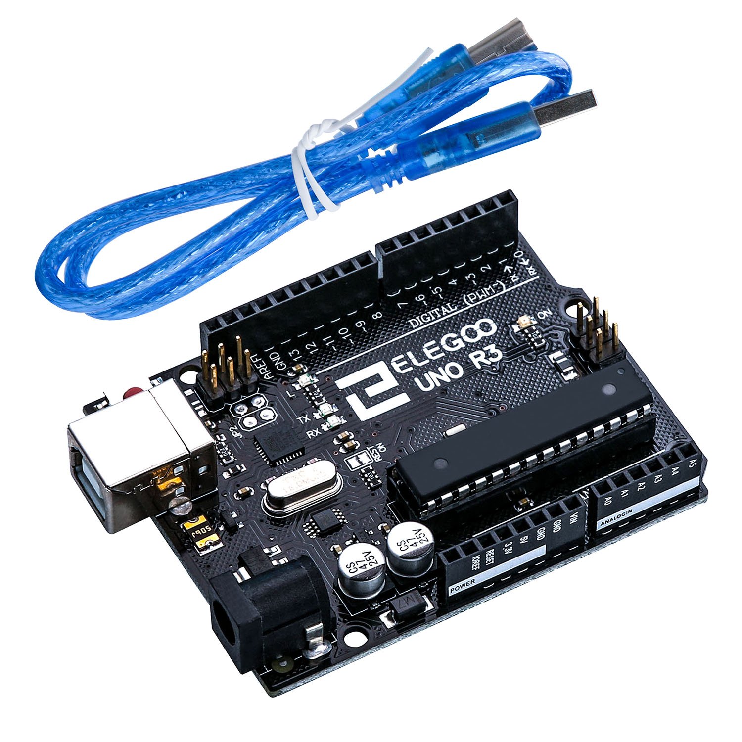
![Home Automation Using Arduino [Beginner Guide]](https://smartify.in/wp-content/uploads/2017/12/ArduinoMain.jpg)


 Firstly, connect the 5V and GND pins to the bus terminals on the breadboard.